


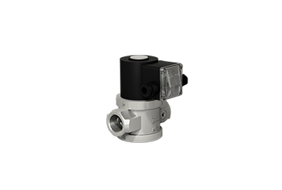
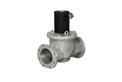
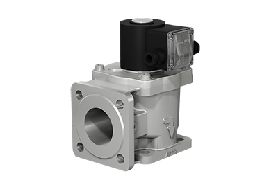
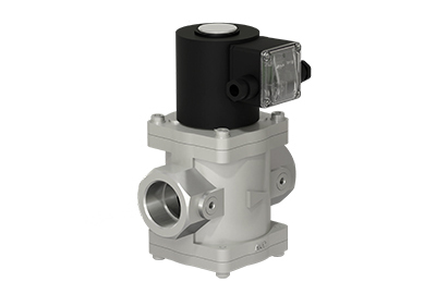
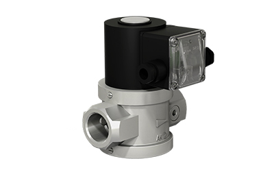
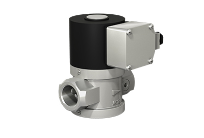
SOLENOID SAFETY GAS VALVES
Solenoid safety gas valve (the valve) is a device designed for usage in systems where remote control of the flow of non-aggressive gaseous medium and liquids is required.
OPERATING PRESSURE:
Operating pressure range of the valve (ВН and BF type):
- 0 to 6 bar (mPa);
- Operating pressure is a maximum overpressure at which adjusted operating mode is maintained.
NOMINAL DIAMETER:
Nominal diameter range of TERMOBREST valves: 15 to 300 mm. Such wide range of nominal diameter types allows covering all demands of the market of gas equipment of low, medium and high pressure.
INITIAL STATE:
- normally closed (closed in de-energized state);
- normally opened (open in de-energized state).
HOUSING MATERIAL:
- steel: DN15÷300;
- cast iron: DN-150, DN-200;
- aluminum: DN15÷200.
Valves in aluminum and cast iron housings are applied at thermal power facilities (boiler houses, furnace rooms etc.), technical gas lines of different plants and factories (chemical, petrochemical, extractive, food, building materials etc), and also by manufacturers of gas equipment (modular boiler houses, boilers, burners, furnaces, flare facility etc). Low weight, cost and small dimensions make valves in aluminum housings practical in application.
Valves in steel housing are applied primarily at large power plants (heat and thermal power plants, condensation power plants etc). Steel housings are highly resistant to static and dynamic loads due to requirements of equipment application at large power plants.
CLIMATIC VERSIONS:
- -30…+60 °С – operation in irregularly heated space;
- -45…+60 °С – operation under cover;
- -60…+60 °С – operation under cover;
- -60…+60 °С – outdoor operation (only for explosion proof version).
OPERATING ENVIRONMENT TEMPERATURE:
By default, all gas valves manufactured by TERMOBREST are supplied in a version designed for working environment with temperature range from -60 to +70 ° C. By special order the valves can be manufactured for working environment with temperature range from -45 до +120 °С.
BY ITS FUNCTIONALITY AUTOMATIC SOLENOID VALVE CAN BE OF TWO TYPES SHUT-OFF VALVE AND SHUT-OFF CONTROL VALVE:

Shut-off valve

Shut-off control valve
- Shut-off valve ensures fast opening/closing (operation time 1 second max) and is applied in systems, where it is necessary to stop medium flow in emergency situation or by technological requirements. Also such valve is applied to control medium supply in gas facilities.
- Shut-off control valve ensures fast opening/closing as well as adjustment of the medium pass in open state of the valve. Shut-off control valve is applied to control medium flow, ensuring necessary operating modes of gas facilities and devices. Control of medium adjustment can be both in manual and automatic modes.
ADDITIONAL FUNCTIONS AND DEVICES:
Valves of BH and BF type can be equipped with valve’s trim position indicator, which transmits information to the control board or automation about the current state of the trim (open or closed).
Besides that valves can be manufactured with manual start-up function of electric or mechanical type. Manual start-up function ensures guaranteed protection of the device from its inadvertent opening in emergency situation.
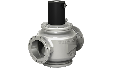
HOUSING TYPE:
Linear (standard)
Angle
Standard (linear version) valves are applied on the straight pipeline sections.
Angle valves are applied at the facilities with limited space (corner sections of the pipeline etc.) and allow reducing number of welding joints and connections during installation.
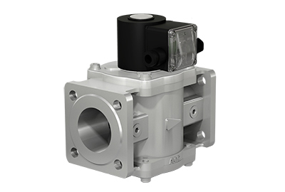
Flange (DN15÷300) connection
Coupling (DN15÷50) connection
Valves with flange connection are manufactured with flanges PN 6 (by default) or PN 16 (on request).
Valves with nominal diameter 15÷50 mm can be manufactured in monoblock unit version, i.e. two and more devices are unified in one housing. Such design ensures maximum functionality with minimal product dimensions.
VERSIONS:
General purpose industrial version
Explosion proof version
General purpose industrial versions of valves are applied at all gas facilities, where there are no special requirements for ensuring explosion safety of electrical equipment.
Explosion proof versions of valves are applied at the facilities and premises with special protective measures requirements upon designing, manufacturing and operating of electrical plants.
Explosion proof electrical equipment is a special type of electrical equipment that is designed to eliminate ignition of the explosive environment surrounding it during the operation of this electrical equipment.
-------------------------------------
If you need help to select necessary equipment, you should visit our web-site or contact our specialists by e-mail info@termobrest.ru or by phone:
+375 (162) 53-64-13 (technical consultation line);
+375 (162) 53-64-76 (sales and logistics department).
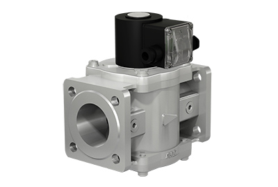
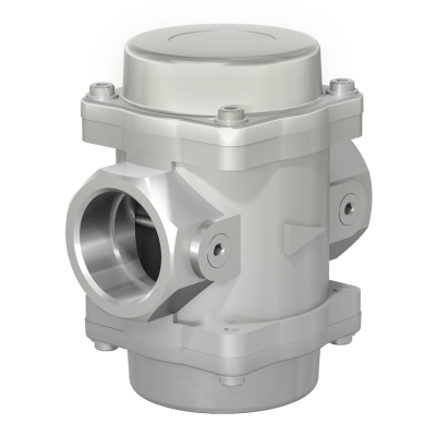
GAS FILTERS
Gas filter is a device designed for gas purification from mechanical particles (dust, rust (corrosion), sand fire scale and other solid particles) and it is installed in front of the shut-off and control fittings unit of gas-burning devices of hot water boilers, heat generators, infrared heaters and other gas-fired installations. It can be applied in measuring instruments (flow meters, meters, manometers, etc.), gas household heating appliances (gas stoves, boilers, direct-flow water heaters, etc.) in gas control units and installations, as well as in other technological gas-air lines, where the operating environment purification from the mechanical particles is required.
An application of gas filters on the pipeline allows a significant service life increase and reliability of the shut-off and control fittings unit, measuring instruments and other devices.
OPERATING PRESSURE:
Gas filters (FH series) are manufactured in versions with maximum operating pressure up to 3 bar (0.3 MPa), up to 6 bar (0.6 MPa) and up to 16 bar (1.6 MPa). Maximum operating pressure is the highest overpressure, when the declared filtration characteristics of the operating environment are provided.
DIAMETER NOMINAL:
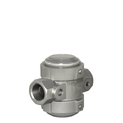
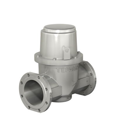
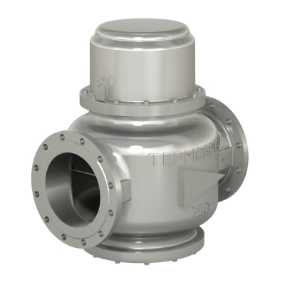
From 15 up to 300 mm
HOUSING MATERIAL:
- steel: DN 15÷300;
- iron cast: DN 150, DN 200;
- aluminum: DN 15÷200.
CLIMATIC VERSION:
- -30…+60 °С version – installation in irregularly heated rooms;
- -45…+60 °С version – installation under roof;
- -60…+60 °С version – installation under roof;
- -60…+60 °С version – outdoor installation.
HOUSING VERSION:
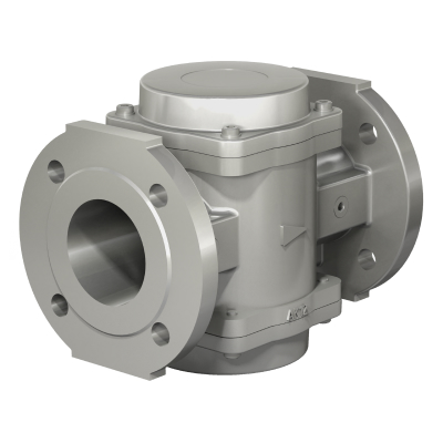
Linear (standard) version
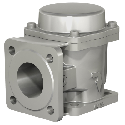
Angle version
Standard (linear) version of gas filters is applied onto the straight sections of the pipeline. Angle version of the filter is used at facilities with limited space (gas-distributing plant, distribution pressure reducing station, etc.). Application of the angle version can reduce the number of welds and joints when arranging the corner sections of the pipeline.
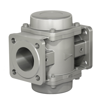
Flange connection (DN15÷300)
Coupling connection (DN15÷50)
Gas filters with flange connection are manufactured with PN 6 (standard) or PN 16 (upon request) flanges.
FILTRATION DEGREE:
TERMOBREST filters are manufactured in standard version with a filtration degree of 50 microns.
We can also produce filters with different filtration degrees: 2 microns, 5 microns, 10 microns, 20 microns, 400 microns, 600 microns, 800 microns.
THERE ARE TWO TYPES OF FILTERING ELEMENTS (CARTRIDGES), WHICH ARE USED IN THE FH SERIES MODELS:
- Filtering pad - is a fibro porous polymer material that provides fine filtration (from 2 up to 50 microns) and it has an improved operational factor in terms of strength, permeability and rigidity compared with other types of fine purification filtering elements. Servicing (cleaning) of such filtering element can be carried out by blowing with compressed air or rinsing in water using detergents;
- Strainer - is a stainless steel grid with a mesh of various sizes, for example, 400 microns, 600 microns, 800 microns. It has low resistance factor, long service life, the replacement is not required and it can be cleaned several times.
CONTROL OF FILTERING PADS (ELEMENTS) CONTAMINATION DEGREE:
To control the contamination degree (pressure drop) of filtering element different types of contamination indicators can be installed on the filter:

Fig. 1
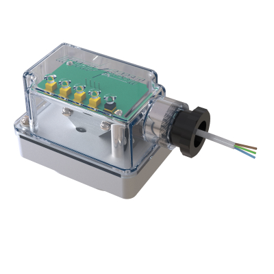
Fig. 2
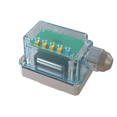
Fig. 3
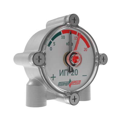
Fig. 4
- Mechanical type of contamination indicator – control of the degree of contamination of the filtering element is carried out visually, using to the inspection window overlap by the indicator element;
- Electric type of contamination indicator with power source mains-operated 24V AC/DC – filtering element contamination control is carried out visually on the LED scale, as well as using a feedback signal (4…20 mA) to the automatic equipment;
- Battery-operated electric type of contamination indicator – filtering element contamination control is carried out visually on the LED scale, by pressing the button on the pressure drop indicator housing;
-
Arrow type contamination indicator – control of the degree of contamination of the filtering element is carried out on a scale (dial plate) with indicating arrows. The scale is divided into segments that indicate the actual pressure drop on the filter from 0 to 30 kPa. There are the indicating drop values through 5 kPa (0, 5, 10, 15, 20, 25, 30 kPa) on the scale for the convenience of contamination control.
The black arrow indicates the actual pressure drop on the filter at the exact moment of operation. It is required to set manually the permissible pressure drop on the filter using red arrow on the scale. When the black and red arrows reach or coincide, the filtering element should be cleaned or replaced.
Depending on the position of the indicator’s visual scale concerning the direction of gas flow through the filter or pipeline, the arrow type contamination indicators are available in two versions: "left-to-right" and "right-to-left".
ADDITIONAL FUNCTIONS AND DEVICES:
All models of gas filters (DN 25÷300 mm) can be equipped with a condensate outlet for draining condensate without demounting the filter or dismantling it from the pipeline.
-------------------------------------
If you need help to select necessary equipment, you should visit our web-site or contact our specialists by e-mail info@termobrest.ru or by phone:
+375 (162) 53-64-13 (technical consultation line);
+375 (162) 53-64-76 (sales and logistics department).