


GAS FILTERS
Gas filter is a device designed for gas purification from mechanical particles (dust, rust (corrosion), sand fire scale and other solid particles) and it is installed in front of the shut-off and control fittings unit of gas-burning devices of hot water boilers, heat generators, infrared heaters and other gas-fired installations. It can be applied in measuring instruments (flow meters, meters, manometers, etc.), gas household heating appliances (gas stoves, boilers, direct-flow water heaters, etc.) in gas control units and installations, as well as in other technological gas-air lines, where the operating environment purification from the mechanical particles is required.
An application of gas filters on the pipeline allows a significant service life increase and reliability of the shut-off and control fittings unit, measuring instruments and other devices.
OPERATING PRESSURE:
Gas filters (FH series) are manufactured in versions with maximum operating pressure up to 3 bar (0.3 MPa), up to 6 bar (0.6 MPa) and up to 16 bar (1.6 MPa). Maximum operating pressure is the highest overpressure, when the declared filtration characteristics of the operating environment are provided.
DIAMETER NOMINAL:
From 15 up to 300 mm
HOUSING MATERIAL:
- steel: DN 15÷300;
- iron cast: DN 150, DN 200;
- aluminum: DN 15÷200.
CLIMATIC VERSION:
- -30…+60 °С version – installation in irregularly heated rooms;
- -45…+60 °С version – installation under roof;
- -60…+60 °С version – installation under roof;
- -60…+60 °С version – outdoor installation.
HOUSING VERSION:
Linear (standard) version
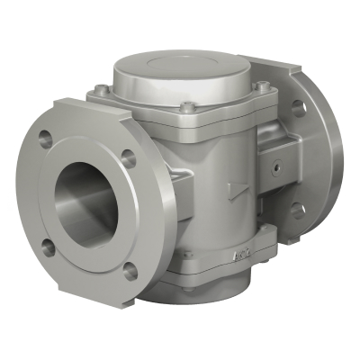
Angle version
Standard (linear) version of gas filters is applied onto the straight sections of the pipeline. Angle version of the filter is used at facilities with limited space (gas-distributing plant, distribution pressure reducing station, etc.). Application of the angle version can reduce the number of welds and joints when arranging the corner sections of the pipeline.
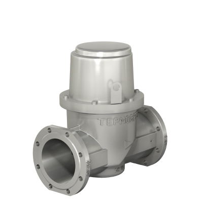
Flange connection (DN15÷300)
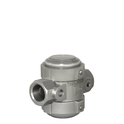
Coupling connection (DN15÷50)
Gas filters with flange connection are manufactured with PN 6 (standard) or PN 16 (upon request) flanges.
FILTRATION DEGREE:
TERMOBREST filters are manufactured in standard version with a filtration degree of 50 microns.
We can also produce filters with different filtration degrees: 2 microns, 5 microns, 10 microns, 20 microns, 400 microns, 600 microns, 800 microns.
THERE ARE TWO TYPES OF FILTERING ELEMENTS (CARTRIDGES), WHICH ARE USED IN THE FH SERIES MODELS:
- Filtering pad - is a fibro porous polymer material that provides fine filtration (from 2 up to 50 microns) and it has an improved operational factor in terms of strength, permeability and rigidity compared with other types of fine purification filtering elements. Servicing (cleaning) of such filtering element can be carried out by blowing with compressed air or rinsing in water using detergents;
- Strainer - is a stainless steel grid with a mesh of various sizes, for example, 400 microns, 600 microns, 800 microns. It has low resistance factor, long service life, the replacement is not required and it can be cleaned several times.
CONTROL OF FILTERING PADS (ELEMENTS) CONTAMINATION DEGREE:
To control the contamination degree (pressure drop) of filtering element different types of contamination indicators can be installed on the filter:

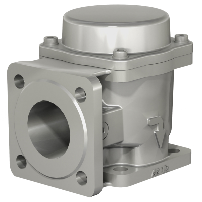
Fig. 1
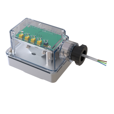
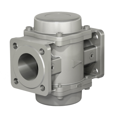
Fig. 2
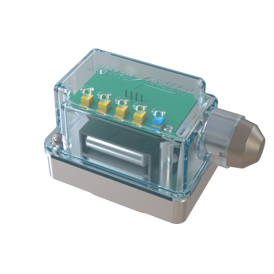
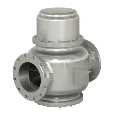
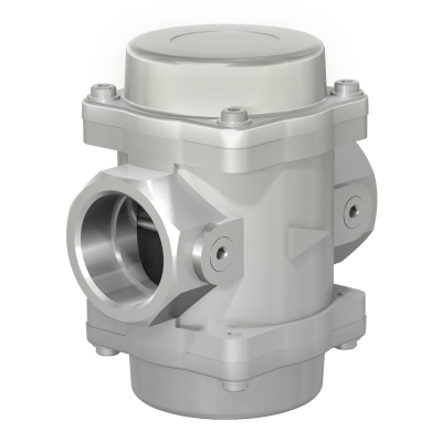
Fig. 3
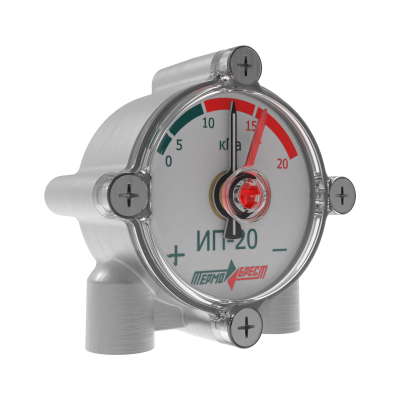
Fig. 4
- Mechanical type of contamination indicator – control of the degree of contamination of the filtering element is carried out visually, using to the inspection window overlap by the indicator element;
- Electric type of contamination indicator with power source mains-operated 24V AC/DC – filtering element contamination control is carried out visually on the LED scale, as well as using a feedback signal (4…20 mA) to the automatic equipment;
- Battery-operated electric type of contamination indicator – filtering element contamination control is carried out visually on the LED scale, by pressing the button on the pressure drop indicator housing;
-
Arrow type contamination indicator – control of the degree of contamination of the filtering element is carried out on a scale (dial plate) with indicating arrows. The scale is divided into segments that indicate the actual pressure drop on the filter from 0 to 30 kPa. There are the indicating drop values through 5 kPa (0, 5, 10, 15, 20, 25, 30 kPa) on the scale for the convenience of contamination control.
The black arrow indicates the actual pressure drop on the filter at the exact moment of operation. It is required to set manually the permissible pressure drop on the filter using red arrow on the scale. When the black and red arrows reach or coincide, the filtering element should be cleaned or replaced.
Depending on the position of the indicator’s visual scale concerning the direction of gas flow through the filter or pipeline, the arrow type contamination indicators are available in two versions: "left-to-right" and "right-to-left".
ADDITIONAL FUNCTIONS AND DEVICES:
All models of gas filters (DN 25÷300 mm) can be equipped with a condensate outlet for draining condensate without demounting the filter or dismantling it from the pipeline.
-------------------------------------
If you need help to select necessary equipment, you should visit our web-site or contact our specialists by e-mail info@termobrest.ru or by phone:
+375 (162) 53-64-13 (technical consultation line);
+375 (162) 53-64-76 (sales and logistics department).
MOTORIZED GAS VALVES
Motorized gas valve is designed as regulating device and is intended for usage in automatic remote-control systems of gas burning installations to control and safeguard streams of various gas mediums including natural gas, hydro-carbonated gases, gaseous phases of liquefied gas, compressed air and other non-aggressive gases.
Note! Motorized valve is not a shut-off device. It is designed and applied for smooth regulation of gas flow.
OPERATING PRESSURE
- From 0 to 6 bar (up to 0.6 MPa);
HOUSING VERSIONS (two types):

Type 1. Motorized regulating gas valve – a rotary cylinder serves as a working (regulating) member that provides the smooth change of the gas volume flow rate from 0.05% (in a closed position) up to 100% (in a fully opened position).
DIAMETER NOMINAL:
- DN40÷200.
HOUSING MATERIAL:
- aluminum: DN40÷100;
- steel: DN40÷200.
OPERATING ENVIRONMENT TEMPERATURE:
- -60...+70 °C.

Type 2. Butterfly-type-gas valve – a rotary throttle serves as a working (regulating) member that provides the smooth change of the gas volume flow rate from 0.5% (in a closed position) up to 100% (in a fully opened position).
DIAMETER NOMINAL:
- DN15÷300.
HOUSING MATERIAL:
- aluminum: DN15÷200;
- steel: DN150÷300.
OPERATING ENVIRONMENT TEMPERATURE:
- -60...+120°C.
OPERATION MODE:

Power drive type

Manual type
In power drive type models, the flow rate control of the amount of passing gas through the motorized gas valve is controlled by the following types of actuators:
- «Regada» (Slovak Republic)
- «Belimo» (Switzerland)
- «Siemens» (Germany)
- and other (upon request);
In manual type models, the flow rate control of the amount of passing gas is controlled by turning the control handle attached to the output end of the shaft. The scale shows: opening angle in degrees, arrows and signs "+" and "-". When turning the control handle towards the "+" sign, the amount of passing gas increases; when turning towards the "-" sign, the gas flow decreases.
The extreme control of handle positions, corresponding to the minimum and maximum gas flow rates, are limited by stops.
During operation, if necessary, the control handle can be dismantled and reinstalled.
REGULATION MODE (for power drive type models):
Proportional regulation. The following actuators are applied:
- «Regada» (SP0, SP1, SP2). The actuator is operated when the power source 220 V, 50 Hz is applied. The actuators are equipped with 4 (four) position limit switches and feedback transmitter. The type of the feedback transmitter: resistive type 2000 Ohm, resistive type 100 Ohm, current type 4...20 mA.
- «Belimo» TF230-S, LF230-S, SF230A-S2; «Siemens» GMA321.1E, GCA321.1E. The actuator is operated when the power source 220 V, 50 Hz is applied. The electric power drive is equipped with the reflexive spring. When the main voltage is removed, the energy stored in the spring, retracts the motorized gas valve into initial position.
Proportional regulation. The following actuators are applied:
- «Belimo» TF230-S, LF230-S, SF230A-S2; «Siemens» GMA321.1E, GCA321.1E. The actuator is operated when the power source 220 V, 50 Hz is applied. The electric power drive is equipped with the reflexive spring. When the main voltage is removed, the energy stored in the spring, retracts the motorized gas valve into initial position.
CLIMATIC VERSION:
- -30…+50 °С – operation in irregularly heated rooms,
- -45…+50 °С – operation under roof,
- -60…+60 °С – outdoor operation (for manual type models);
MOUNTING POSITION:
- Onto horizontal and vertical pipelines.
VERSIONS:

General industrial usage

Explosion proof
Products in general industrial usage version are applied at all gas facilities where there are no special requirements to ensure the explosion safety of the electrical equipment;
Explosion-proof fitting units are applied at facilities and rooms where there are or may be formed explosive mixtures in the amount that requires special protection measures of the design, manufacture and operation of the electrical installations. To ensure safety in these zones the explosion-proof electrical equipment should be used.
Explosion-proof electrical equipment is the electrical equipment with such a construction as to eliminate the ignition of the surrounding explosive environment due to the operation of this electrical equipment.
-------------------------------------
If you need help to select necessary equipment, you should visit our web-site or contact our specialists by e-mail info@termobrest.ru or by phone:
+375 (162) 53-64-13 (technical consultation line);
+375 (162) 53-64-76 (sales and logistics department).